
Product Description
Drive Pipe Spline Shaft Disc Flange Gear Rubber Jaw Motor Spacer Beam Rigid Fluid Chain Nm Mh HRC Pin Fenaflex Spacer Elastomeric Flexible Gear Coupling
Main products
Coupling refers to a device that connects 2 shafts or shafts and rotating parts, rotates together during the transmission of motion and power, and does not disengage under normal conditions. Sometimes it is also used as a safety device to prevent the connected parts from bearing excessive load, which plays the role of overload protection.
Couplings can be divided into rigid couplings and flexible couplings.
Rigid couplings do not have buffering property and the ability to compensate the relative displacement of 2 axes. It is required that the 2 axes be strictly aligned. However, such couplings are simple in structure, low in manufacturing cost, convenient in assembly and disassembly, and maintenance, which can ensure that the 2 axes are relatively neutral, have large transmission torque, and are widely used. Commonly used are flange coupling, sleeve coupling and jacket coupling.
Flexible coupling can also be divided into flexible coupling without elastic element and flexible coupling with elastic element. The former type only has the ability to compensate the relative displacement of 2 axes, but cannot cushion and reduce vibration. Common types include slider coupling, gear coupling, universal coupling and chain coupling; The latter type contains elastic elements. In addition to the ability to compensate the relative displacement of 2 axes, it also has the functions of buffering and vibration reduction. However, due to the strength of elastic elements, the transmitted torque is generally inferior to that of flexible couplings without elastic elements. Common types include elastic sleeve pin couplings, elastic pin couplings, quincunx couplings, tire type couplings, serpentine spring couplings, spring couplings, etc
Company Profile
Our Factory
Application – Photos from our partner customers
/* January 22, 2571 19:08:37 */!function(){function s(e,r){var a,o={};try{e&&e.split(“,”).forEach(function(e,t){e&&(a=e.match(/(.*?):(.*)$/))&&1
Temperature and Environmental Limits for Various Beam Coupling Materials
The temperature and environmental limits of beam coupling materials depend on their specific composition and properties. Different materials have varying degrees of resistance to temperature extremes, chemicals, humidity, and other environmental factors. Here are some common beam coupling materials and their associated temperature and environmental limits:
- 1. Stainless Steel:
Stainless steel beam couplings are known for their excellent mechanical properties and resistance to corrosion. They can typically operate within a wide temperature range, from -40°C to 300°C (-40°F to 572°F). Stainless steel is also resistant to most chemicals, making it suitable for various environments, including industrial and outdoor applications.
- 2. Aluminum:
Aluminum beam couplings offer lightweight construction and moderate mechanical properties. They have a more limited temperature range compared to stainless steel, typically operating between -20°C to 120°C (-4°F to 248°F). While aluminum has good corrosion resistance in certain environments, it is not as durable as stainless steel in harsh conditions.
- 3. Brass:
Brass beam couplings have reasonable mechanical properties and corrosion resistance. They are suitable for applications with temperatures ranging from -20°C to 100°C (-4°F to 212°F). Brass is more susceptible to corrosion in certain environments, so it is essential to consider the specific application’s conditions.
- 4. Plastic/Polymer:
Beam couplings made from plastic or polymer materials offer lightweight and cost-effective solutions. However, their temperature limits are more restricted compared to metal couplings. They typically operate between -30°C to 80°C (-22°F to 176°F). These couplings may not be suitable for high-temperature or chemically aggressive environments.
- 5. Carbon Steel:
Carbon steel beam couplings are known for their strength and mechanical properties. They generally operate between -40°C to 120°C (-40°F to 248°F). Carbon steel is vulnerable to corrosion, so it may not be ideal for applications in corrosive or humid environments without proper protection.
It’s crucial to consider the temperature and environmental conditions of your specific application when selecting a beam coupling material. Choosing a material that can withstand the intended operating conditions will ensure the longevity and reliable performance of the coupling.
Additionally, keep in mind that various beam coupling manufacturers may offer specific variations of materials with different properties and limits. Always refer to the manufacturer’s datasheets and technical documentation for precise information on the temperature and environmental limits of their beam coupling products.
Beam Couplings Accommodating Different Shaft Diameters and Mounting Configurations
Beam couplings are highly versatile and can accommodate different shaft diameters and mounting configurations, making them suitable for a wide range of motion control applications. Their design and construction allow for flexibility in adapting to various shaft sizes and mounting setups. Here’s how beam couplings achieve this:
- Multiple Bore Sizes:
Beam couplings are available in various bore sizes to match different shaft diameters. Manufacturers offer a wide range of coupling sizes, ensuring that there is an appropriate coupling size available to fit the specific shaft diameter of your application. Some beam couplings come with set screws or clamps that securely fasten onto the shafts, accommodating shafts of different sizes within the coupling’s specified range.
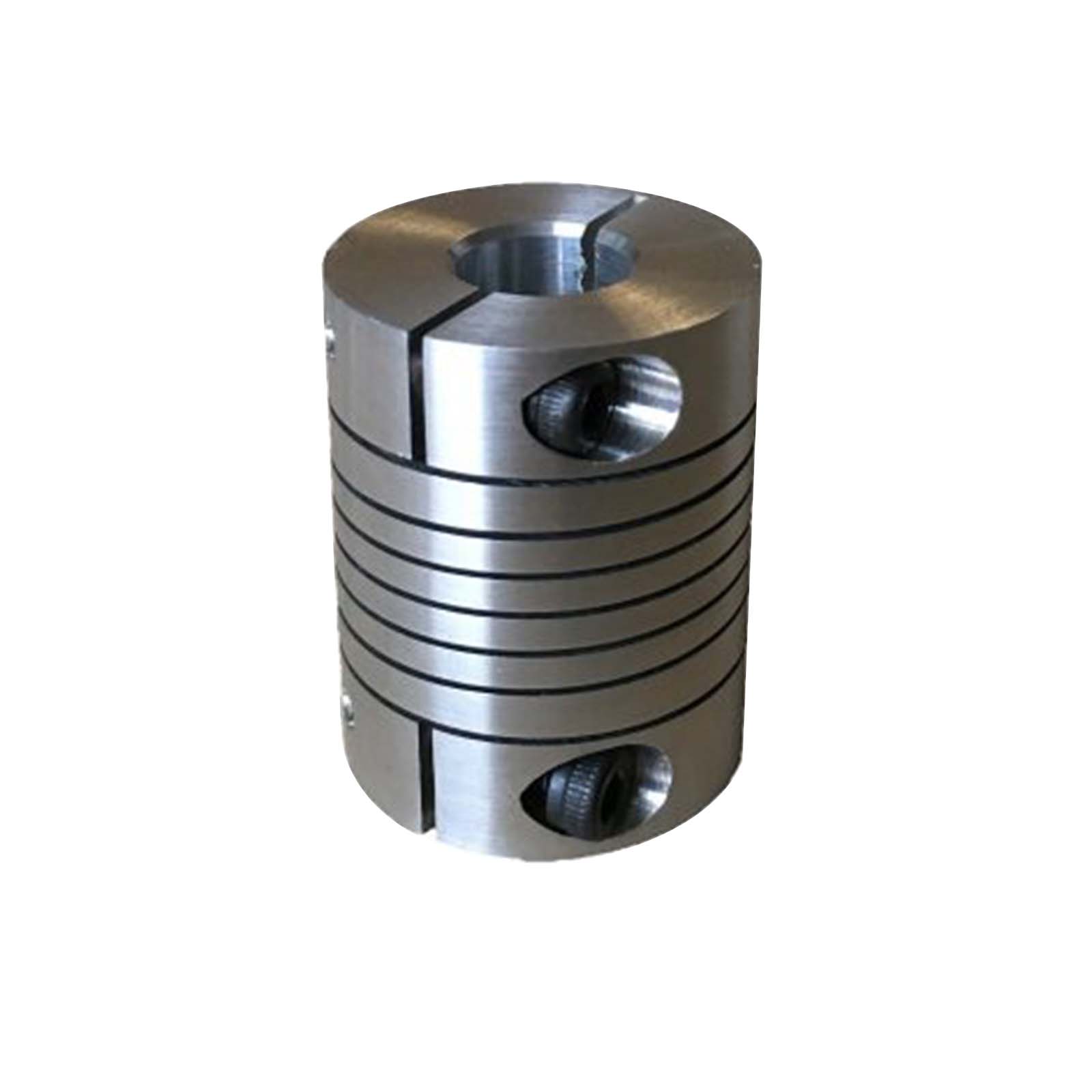
- Clamp or Set Screw Mounting:
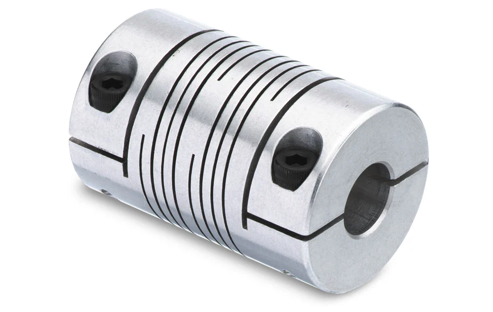
Beam couplings commonly employ clamp or set screw mounting methods to connect to the shafts. Clamp-style couplings use split hubs that can be tightened around the shaft with screws, providing a secure and concentric connection. Set screw couplings, on the other hand, utilize screws to press against the shaft, achieving a firm and non-marring grip.
- Step Bores and Adapters:
In cases where the shafts have significantly different diameters or when transitioning between metric and imperial measurements, some beam couplings offer step bores or adapter options. Step bores feature multiple bore sizes within the same coupling, allowing for flexibility in accommodating various shaft diameters. Adapters are also available to bridge the gap between different shaft sizes.
- Customization:
For unique or specialized applications, manufacturers may offer customization options for beam couplings. This could include modifying the bore sizes, lengths, or other design parameters to suit specific shaft dimensions and mounting configurations.
- Compatibility with Misalignment:
Beam couplings are designed to handle misalignment between the shafts. This characteristic provides additional flexibility during installation, as it can compensate for slight positioning errors or misalignment during assembly.
When selecting a beam coupling for your application, ensure that the chosen coupling size matches the shaft diameters within the specified range. Also, consider the mounting method that best suits your setup, whether it’s clamp-style or set screw-type. For applications with specific requirements, such as adapting between different shaft sizes, explore options with step bores or adapters or inquire about custom solutions from coupling manufacturers.
Overall, the ability of beam couplings to accommodate different shaft diameters and mounting configurations makes them a versatile and widely-used choice in motion control systems across various industries.
Differences between Single-Beam and Multi-Beam Couplings
Single-beam and multi-beam couplings are two common types of beam couplings used in motion control applications. While they both provide flexibility for misalignment compensation, they have distinct differences in design and performance. Let’s explore these differences:
- Structure:
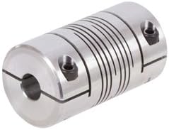
A single-beam coupling consists of a single helical beam that connects the two shafts. It is a straightforward design with a single helix providing angular misalignment compensation. On the other hand, a multi-beam coupling has multiple helical beams arranged in parallel around the circumference of the coupling. The multiple beams increase its flexibility and enable compensation for angular, axial, and parallel misalignment.
- Misalignment Compensation:
Both single-beam and multi-beam couplings are capable of compensating for misalignment between connected shafts. However, the level of compensation differs between the two types. Single-beam couplings are more suitable for applications with primarily angular misalignment. They can handle small amounts of axial and parallel misalignment but are less effective than multi-beam couplings in this regard. Multi-beam couplings, with their multiple beams, can efficiently accommodate more extensive misalignment in all three axes, making them suitable for applications with more complex misalignment requirements.
- Torsional Rigidity:
Single-beam couplings typically have lower torsional rigidity compared to multi-beam couplings. This means that single-beam couplings may exhibit slightly more torsional flexibility and compliance under torque compared to their multi-beam counterparts. As a result, multi-beam couplings are often preferred in applications where high torsional rigidity is essential to maintain precise motion control and minimize backlash.
- Applications:
The choice between single-beam and multi-beam couplings depends on the specific requirements of the application. Single-beam couplings are commonly used in applications where space is limited, and primarily angular misalignment needs to be compensated. They are suitable for less demanding misalignment scenarios and can be found in various motion control systems, including small automation machinery and robotics.
Multi-beam couplings are chosen for applications that require more comprehensive misalignment compensation. They excel in situations where misalignment can occur in multiple axes and are often used in precision motion control systems, optical equipment, and applications with high torsional rigidity and accuracy requirements.
In summary, single-beam and multi-beam couplings both offer flexibility for misalignment compensation in motion control systems. Single-beam couplings are simple, space-efficient, and suitable for applications with primarily angular misalignment. On the other hand, multi-beam couplings provide enhanced misalignment compensation in all three axes and offer higher torsional rigidity, making them ideal for precision applications with more complex misalignment requirements.


editor by CX 2024-04-08